Week 6 – Computer Controlled Machining
Overview
This week, we learned about the CNC milling machine. Our tasks included:
- Complete the lab's safety training as a group.
- Test runout, alignment, fixturing, speeds, feeds, materials, and toolpaths for the machine.
- Individually: design, mill, and assemble something big.
Group Work
Lecturer Antti Mäntyniemi supervised our group work, where we learned the basic safety rules when operating the CNC milling machine and cut out some shapes. He also showed us the design process and we learned about toolpaths and how to prepare the design for milling.
3D Design
As always, we are starting with the 3D design of the idea. I wanted to make something like a coat hanger with two pieces that slot together vertically. One of the pieces would have a slit at the top and the other at the bottom.
To start, I downloaded a silhouette of a simple tree. I imported it to Inkscape to convert it to vector form, and then imported the .svg file to Autodesk Fusion in sketch mode.
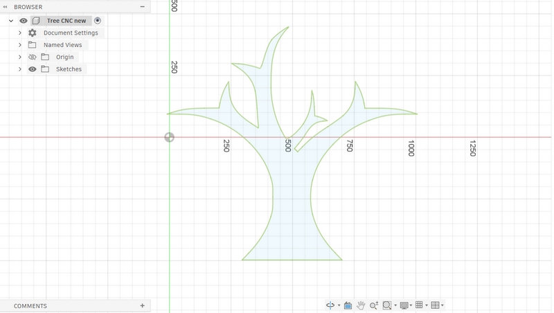
The base wood to be used is around 1.5m long, so I resized the tree to be just around 1m. Although I had resized it in Inkscape, after importing it to Fusion, it had become smaller so I had to resize it again. Then I finished sketch mode and extruded the design by 11mm, which is the thickness of the wood panel that we would be using. Then I replicated the tree.
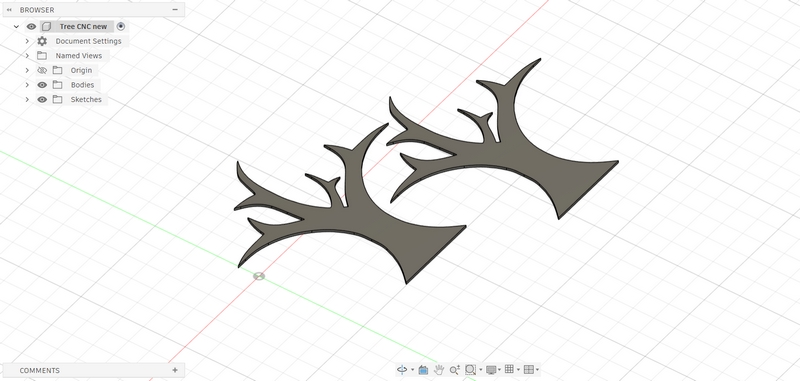
To make the slit, I selected one of the trees and went to sketch mode again, where I created a rectangle. The base of the rectangle aligned with the base of the tree, roughly in the middle. I had to make sure the rectangle didn't cut through a whole branch such it would be separated from the overall piece. I set the width to be 11mm as well, because the slot should be as big as the thickness of the wood panel. The height of the rectangle didn't matter and I set it to be longer than the tree.
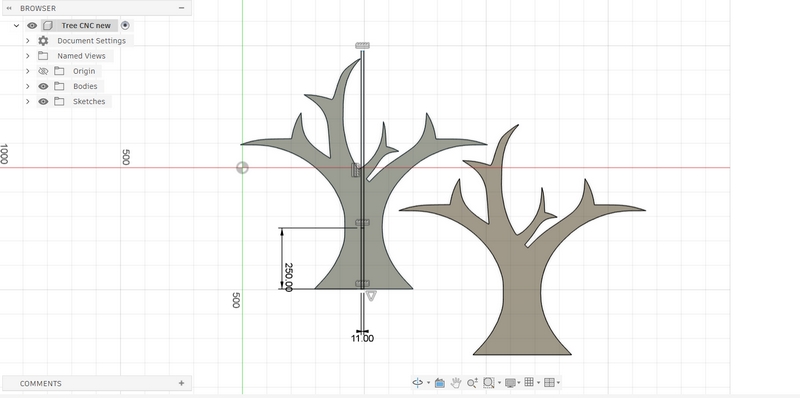
Next, I created a horizontal line across the tree, trimming it so only the part inside the rectangle would be visible. I set it to be 250mm above the base. I repeated the process for the second tree, using the same dimensions. Now, the rectangle was divided into three parts, as you can see in the image above, separated by the horizontal line and the edge of the tree.
I went into 3D mode and for the first tree, I selected the top two parts of the rectangle. I extruded it all the way backwards so there would be a slit on the tree. For the second tree, I extruded the bottom part of the rectangle backwards.
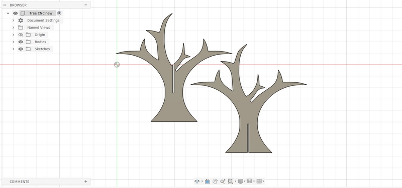
The design was now complete. Next, I had to create a toolpath for the design. Antti walked me through the process.
Creating a Toolpath
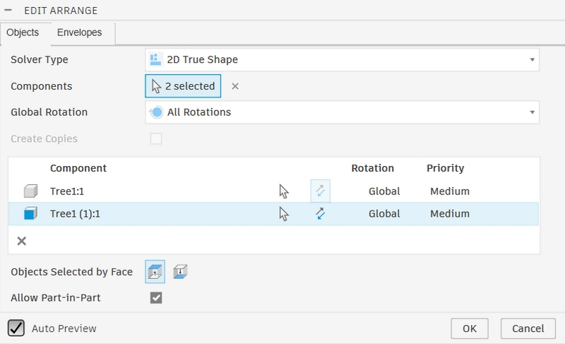
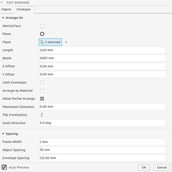
The first step in this process is to convert the bodies to components. I have only two bodies, which I converted and then ungrounded from the parent. Next, I selected Modify -> Arrange and selected the two components to be CNC-machined. I selected the XY-plane from the Envelopes tab, and also set the Length, Width, Frame Width, and Object Spacing.
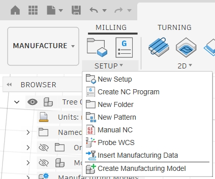
I switched from Design to Manufature mode in the top left corner, and created a new setup.
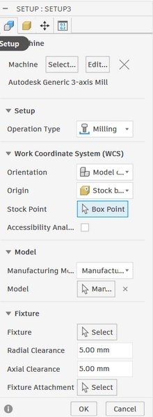
Here, I selected the machine Autodesk Generic 3-axis Mill, which I had downloaded and imported from our Moodle. I also set the Stock Point to be on the bottom left corner.
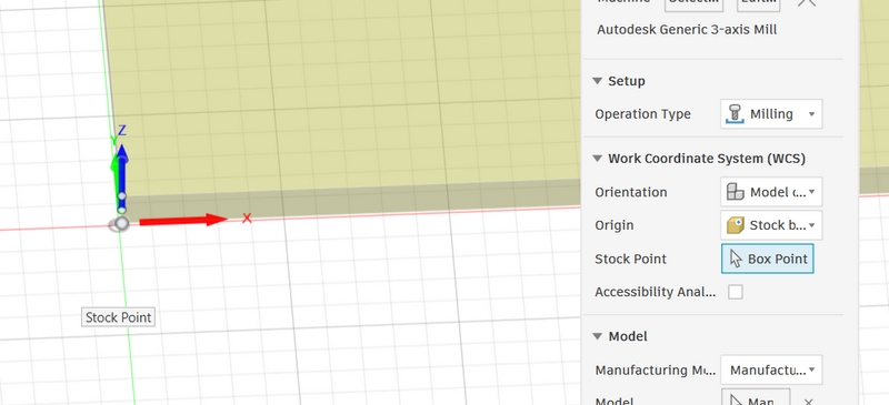
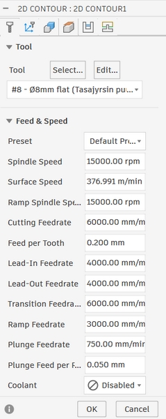
I then selected 2D -> 2D Contour. This is where I selected the tool 8mm flat. This was also downloaded and imported from Moodle. The rest of the settings were preset and left unchanged. The Multi-Axis tab was also unchanged.
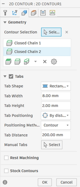
In the third tab under 2D Contour, Geometry, I selected the contours, which are the bottom edge of each component.
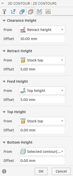
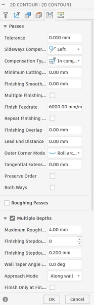
Under Heights tab, I made a few changes to the offset. Also, under Passes Tab, under Multiple Depths, I set the Maximum Roughing Stepdown to be 4mm. This is the maximum depth the tool will cut in each pass.
With everything set up, I can now simulate the cutting process. Choosing Action -> Simulate, you can see the tool cutting the design, and if you choose the Info tab, you can see the position of the tool. This helps to ensure everything is set up correctly, and that the process will work as intended.
Creating the NC file
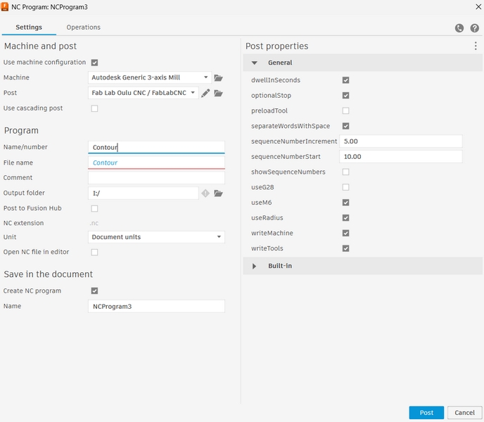
I selected Action -> Post Process to export the design to be milled. It creates a G-code file which compiles every action that the machine is to take in order to complete the cutting process, such as direction, speed, and depth. I saved the file to a USB stick.
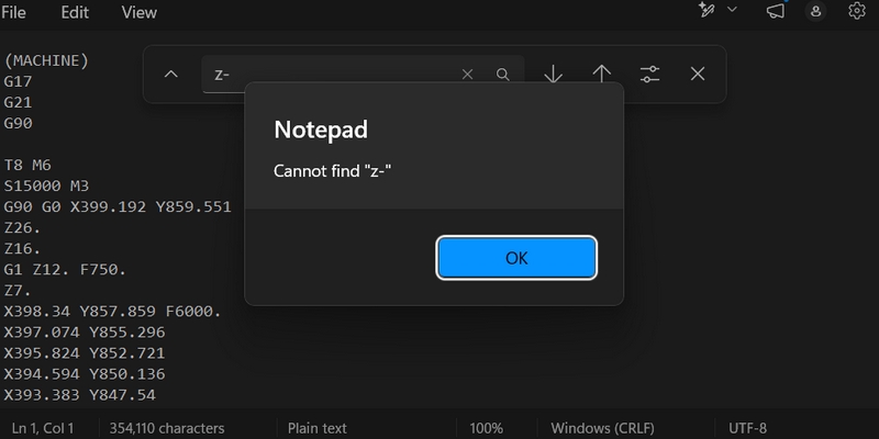
Before running, it is important to check that the machine does not have any unwanted commands. I did so by searching "Z-" and making sure there are no commands with this line. This ensures that the Z-direction of the tool never goes below 0.
When everything seems okay, it is ready to be transferred for the final step.
CNC Milling
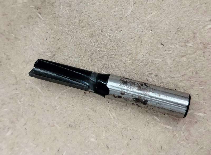
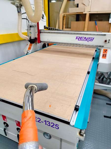
I used an 8mm bit:
Before loading in the wood panel, I vacuumed the area to get rid of wood particles from previous jobs.
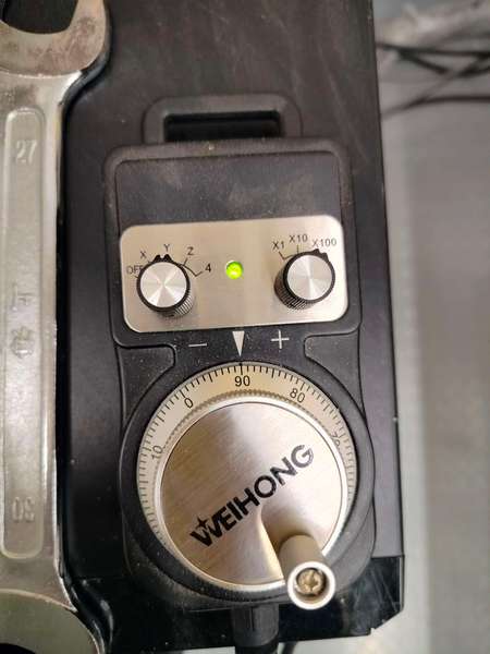
The handwheel is used to move the milling bit around to be calibrated and to set the origin.
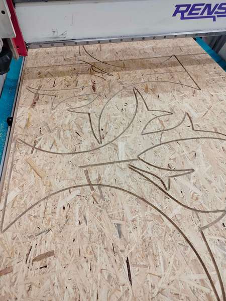
Once the machine was set up, I imported the .nc file to NCStudio. I set up the origin and simulated the movement again. I ran the design and the machine started cutting it. (Warning for loud noise)
The final product:
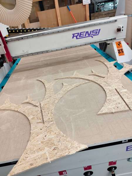
Note that the machine does not cut the design completely. There are bumps where the tool lifts slighlty every few seconds. This is to ensure that the cut part does not separate completely and hence, move around during cutting, causing irregularities. As a result, I had to cut off the bumps manually using a saw, before I was able to take the trees out.
After assembly:
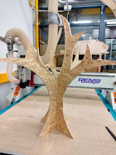
I used a file to remove the remains of the bumps and sanded the edges for a smooth finish. After the task is complete, make sure to clean and vacuum the area again.
Design File
Learning Outcomes
- Using a CNC milling machine
- Creating toolpaths
- 3D designing objects that can be assembled together after building
Reflection
I was mildly intimidated by the huge CNC machine, and was also unsure of what to design as it had to be large. But the process turned out to be quite simple. The only part of this assignment that troubled me was creating the toolpath; it is a little bit complicated and Fusion is quite difficult to navigate around. Other than that, this was my first time working with wood and I was glad to be able to gain this experience.