Week 3 – Computer-Controlled Cutting
Overview
This week, we worked on laser and vinyl cutting. During the first part of the week, we learned how to work the two machines. Then we worked on our assignments:
- Make a press-fit construction kit using laser cutting
- Make something using the vinyl cutter
Group Work
First, we spent some time famialiarising ourselves with the laser cutter and the vinyl cutter. This work was done in groups under the guidance of our instructors, Behnaz and Gleb. We performed several small tasks to learn the basics of laser cutting. We also learned about the safety procedures. This work is documented in the Fab Lab Oulu site.
Task 1 - Press-fit Construction Kit
The laser cutter I used for this assignment is the Epilog Laser Fusion 75W CO2. First, I turned on the device using the power button on the bottom right side. Next, I turned on the air ventilation system. This is needed to get rid of the excess burnt material.
To set up the device for printing, a few steps must be followed. The control panel on the right side of the machine consists of a screen and some buttons. This panel will be used for the initial setup. The laser safety procedure I followed is documented in the above link.
After I have placed my desired material inside the machine, I need to set the origin. It is usually set on the top left corner of the material, making sure there is enough space for the design. Using the arrows, I chose Origin, and then used the joystick to move the jog to the place where I wanted the origin to be. The red pointer can be turned on to make it easier to see where the jog is pointing.
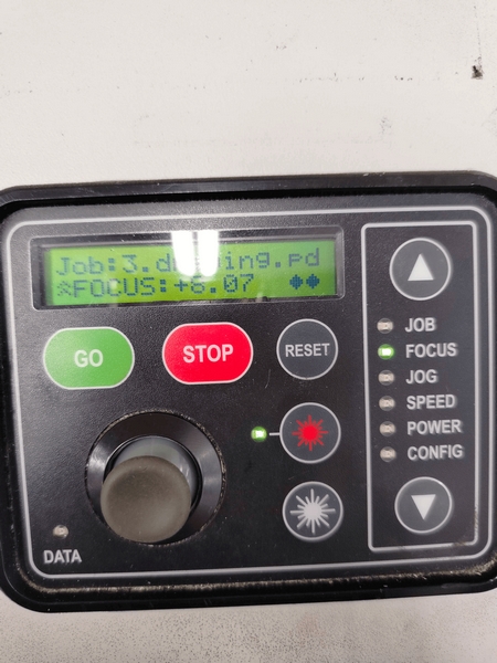
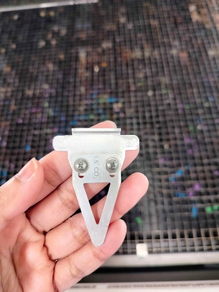
Next, I need to set the focus, which is the distance of the material from the laser. I chose the Focus option and placed the triangular tool on the jog. I used the joystick to move the table up and down. The surface of the material needs to just touch the tip of the tool. Both Origin and Focus settings can be saved by pushing the joystick.
Finally, the machine is ready for printing. Once the design is ready, it is exported for print, and the file shows up on the screen of the control panel when I choose Job. Then, when I press Go, the laser cutter starts cutting.
For this week's assignment, we were asked to build a press-fit construction kit. It's a set of pieces that can be assembled into one or more structures by interlocking them without any kind of adhesive. I had to make several attempts before my final design. My first idea was to make a jewellery/multi-purpose box with a cat theme.
For the top, I went to Sketch mode and made two concentric circles of diameters 20 cm and 17 cm respectively. As Fusion allows you to snap onto the grid, I was able to select the origin as the centre for both circles without having to use the concentric constraint.
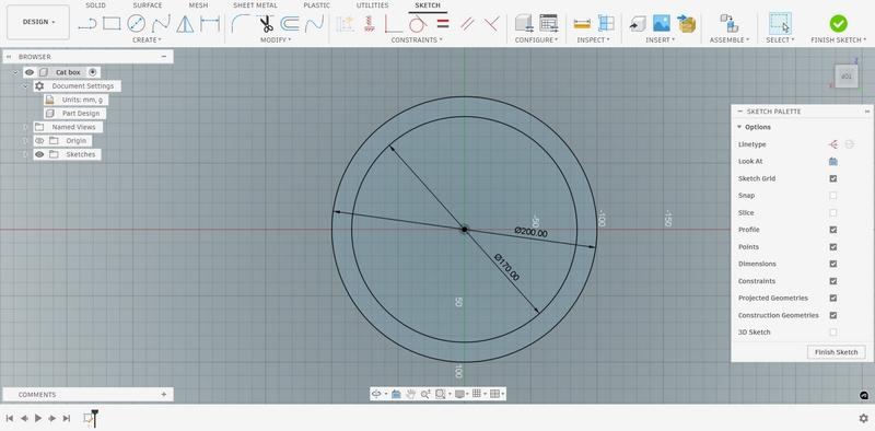
I finished the sketch to save the circles. To draw the slots, I opened the sketch mode again, selecting the same plane. I did not continue in the previous canvas as the circles and the slots should be on different layers. In the new canvas, I made a narrow rectangle with width 3mm, which is the thickness of the material we would be using.
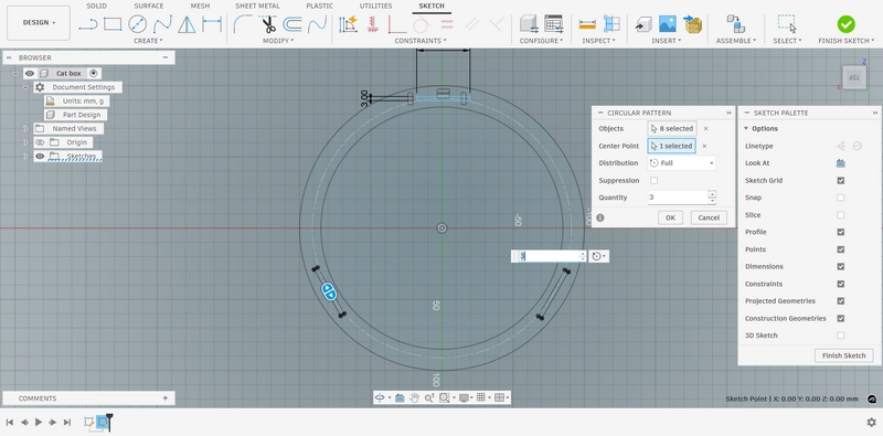
Then, from Create, I chose Circular Pattern.
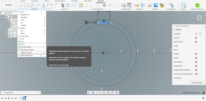
This allows you to draw the rectangles along the circumference of a circle. You can choose the centre through which the rectangles would be drawn, and the number of rectangles. You can use the arrows to select how many rectangles you want.
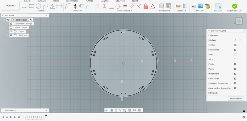
I then made the base of the box in the same way, with only the outer circle and the same number of smaller rectangles.
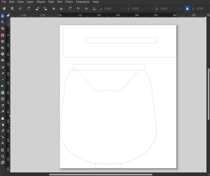
For the side of the box, I wanted some simple cat heads that would slot into the top and the base. I used Inkscape for this stage.
I downloaded a cat silhouette and uploaded it to Inkscape. It would have one rectangle along its ears and one along its neck.
To test if the cats would fit into the slots, I made a separate rectangular piece with a slot that was the same dimension as those in the box.
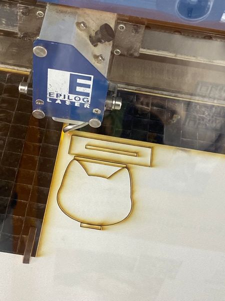
I accounted for the kerf using the measurements from our previous class. Luckily, it fit quite well on the first try, although I forgot to group the cat with the rectangles, so the laser cutter ended up separating them.
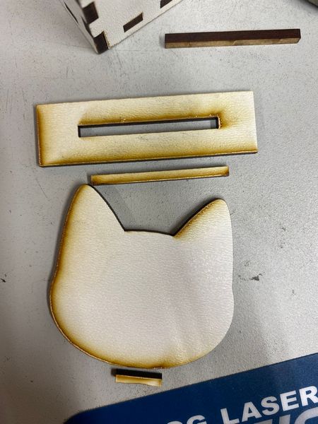
After grouping, I finally made a proper cat piece that fit into the slot. So I proceeded to print the circular parts.
When the cat piece fit into the top and the base of the box, I then went into Inskcape to make ten copies and print them.
Before assembling the pieces, it is important to carefully clean the pieces with hand sanitizer to remove the extra dust. You also need to make sure to wash your hands properly and not to touch your face before doing so. This is an important part of laser safety procedure.
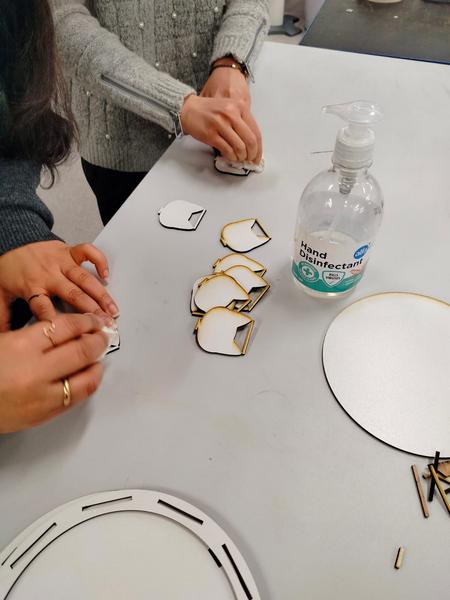
Finally, I fit the pieces together to create the final product:
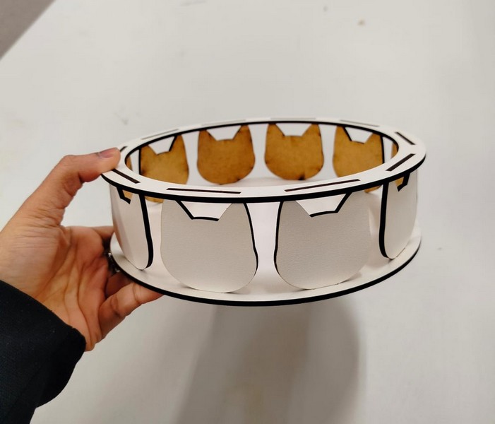
Unfortunately, I failed to realise that this product does not fit one of the criteria of the assignment: "must be able to assemble in multiple ways". So I went on to try and make something different. I had also not calculated the kerf for this project and instead, used the calculations from the tutorial sessions. So I wanted to account for that as well.
After looking at some pictures online for inspiration, I decided to go for a hexagonal shape with slots on the sides. I also wanted to try acryclic instead of wood this time. The first thing I did was cut a small piece with a 30x30mm square inside. Then I used vernier callipers to measure the actual width of the square, and also the width of the space cut.
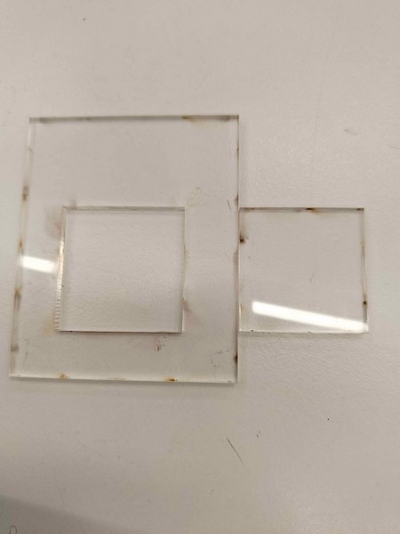
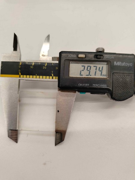
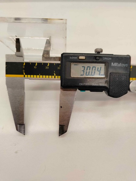
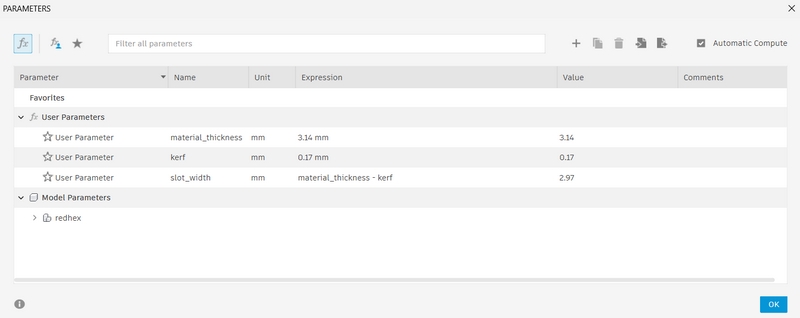
Now, I can measure the kerf, which came to be 0.26. I went to Autodesk Fusion to add this kerf to my design. You can do this by going to Modify -> Change Parameters, and click the + icon to add your own parameters. Three parameters need to be added for laser cutting: material thickness, kerf, and slot width. Slot width is the kerf subtracted from the thickness.
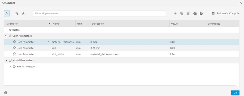
Now I was ready to make my design. I went to sketch mode first, using the horizontal plane, and made a six-sided polygon.
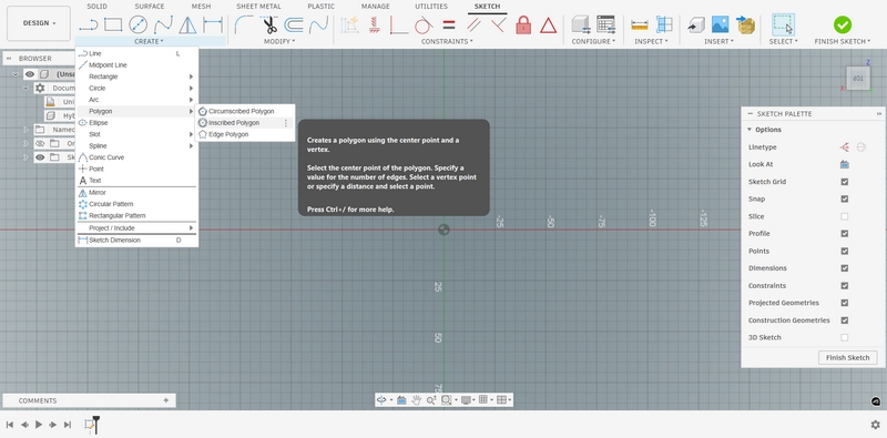
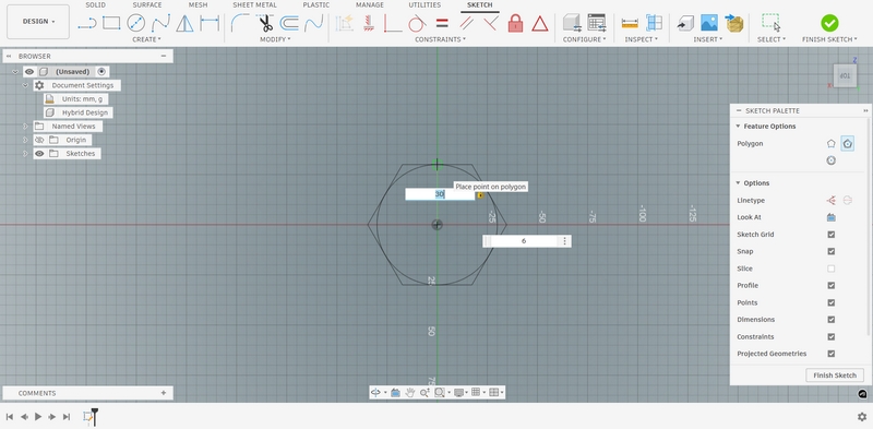
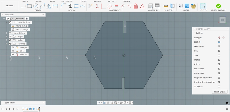
This is where the kerf would come into play. I made a rectangle along one of the edges of the polygon. I chose the height to be 12mm and then set the width to be equal to the "slot_width" parameter. I chose the Circular Pattern as before to repeat the slot twice on the shape.
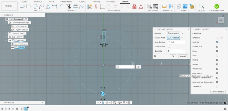
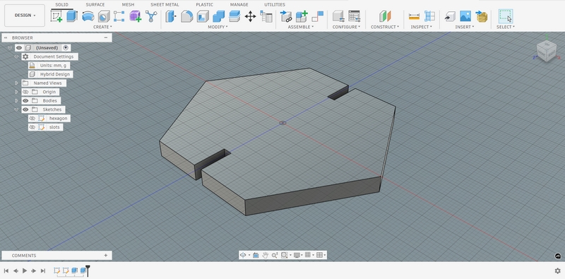
I finished the sketch and extruded the shape to make it 3D. I also extruded the slots inwards to make them disappear and create holes on the shape. Looking back, this step was probably unnecessary as the laser cutter would have worked along the borders and created a slot anyway. But it was a nice way to create a 3D representation of what I was making.
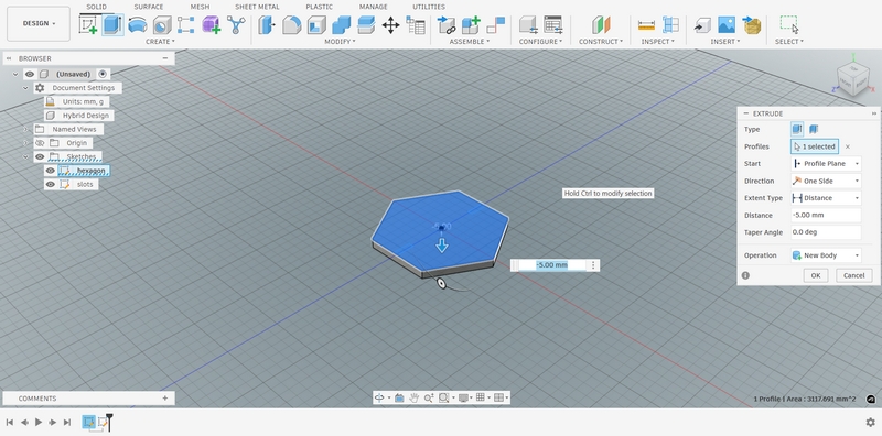
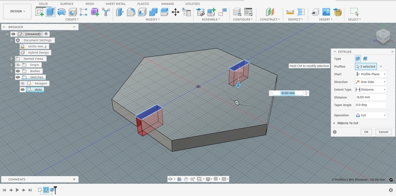
The final 3D and 2D design were as follows:
The next step was, of course, to print the design. I exported the sketch as a .DXF file, which I then opened with Inkscape. I made two copies of the design. However, I ran into a problem when printing. It did not cut the design completely, so it was still attached to the main board, even though I had chosen "3mm Acrylic" on the settings. I ran the print again and after the second cut, it was separated successfully.
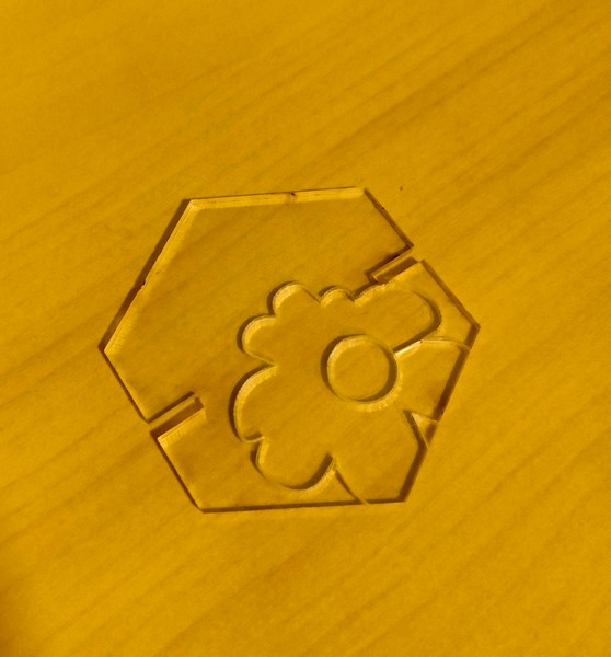
After talking to Behnaz, she suggested that I should lower the speed of the laser as the power was already at 100%. I did so, changing it from 15 to 10, and the laser cut the design successfully this time, although the empty area on the board was limited and I ended up working on top of a previous project by someone else, producing this nice design.
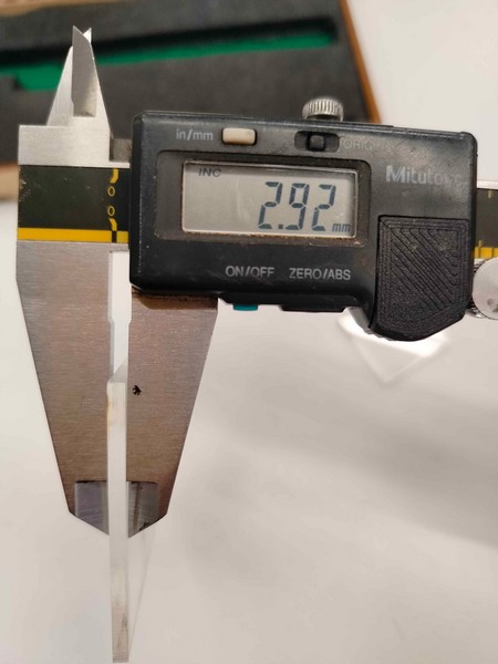
At this point, I realised that I had forgotten to account for the material thickness, even though I had measured it. It was 2.92mm, but when adding the parameters, I had set it to 3mm.
Because I didn't like how the polygon was too big and the slots too small, I decided to redesign the shape. I also chose a different acrylic material this time, a red one which seemed slightly thicker than the transparent one. It also had a lining on the back, which Behnaz said absorbs the burnt material and keeps the final product clean.
I performed the kerf test again, and as you can see this material is indeed marginally thicker.
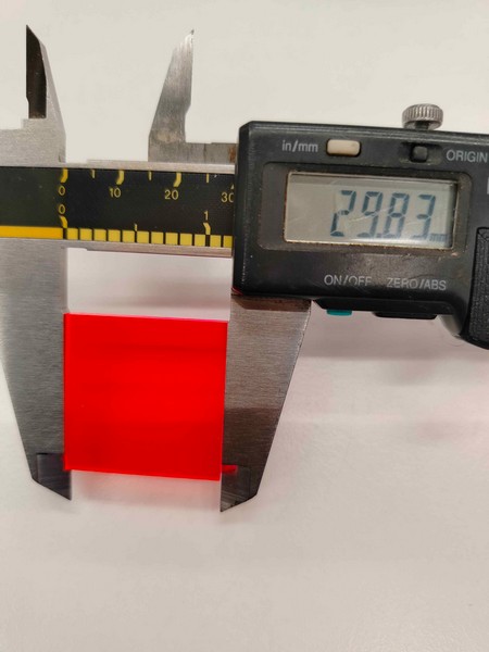
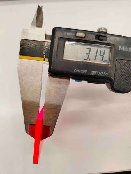
I set up the new parameters for this design, and made a smaller hexagon using the same steps as before.
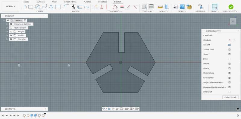
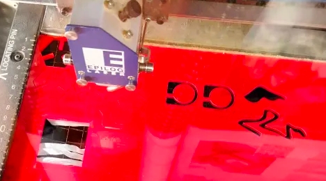
I then exported and printed two copies of this shape. This time, it cut on the first try, without me changing the speed of the laser. I was also happy with the size and the fitting, so I made four more copies. I carefully peeled off the lining and noticed how the final piece was indeed free from any stains.
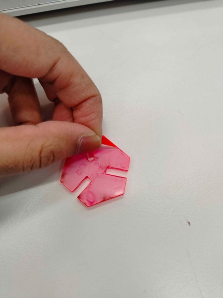
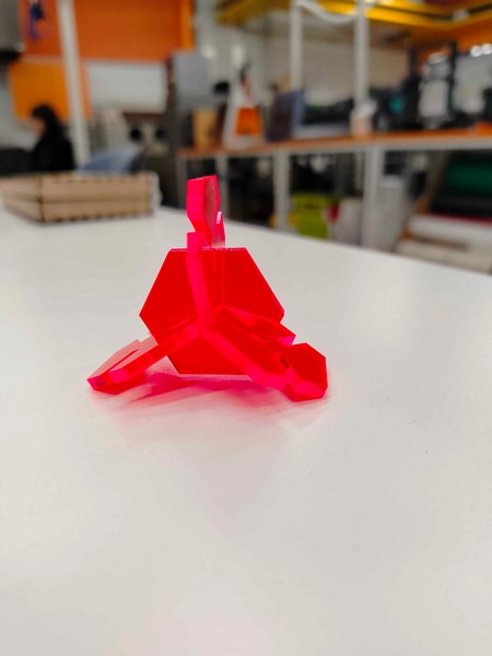
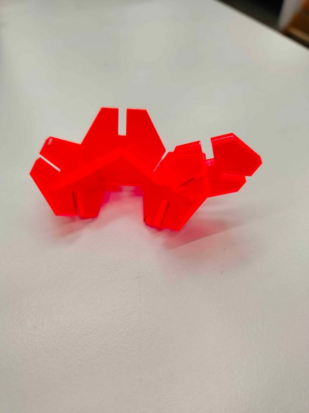
Finally, I was able to attach the pieces and orient them in many different ways.
Task 2 - Vinyl Cutting
Another assignment we had this week was vinyl cutting. One suggestion was to make stickers for our laptop. However, because I already have too many stickers at home that I have no space for, I decided to go for the fabric route.
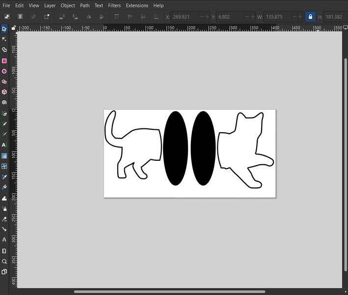
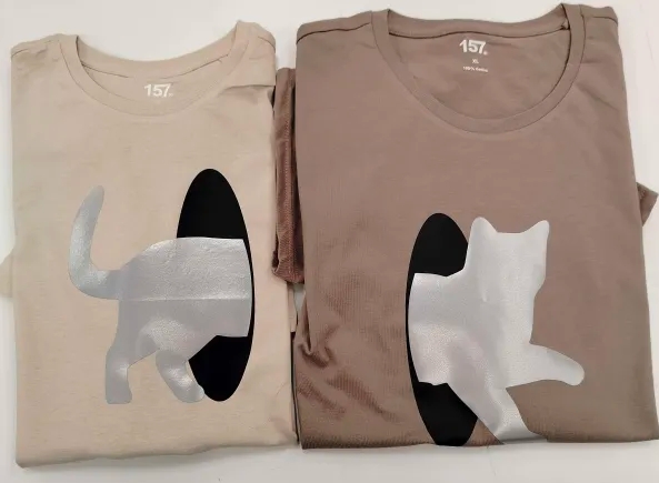
My idea was to make matching T-shirts for me and my partner. The final idea I settled on was a cat walking from one T-shirt to the other through a tunnel. For this, I made two ovals on Inkscape and downloaded a cat side profile silhouette.
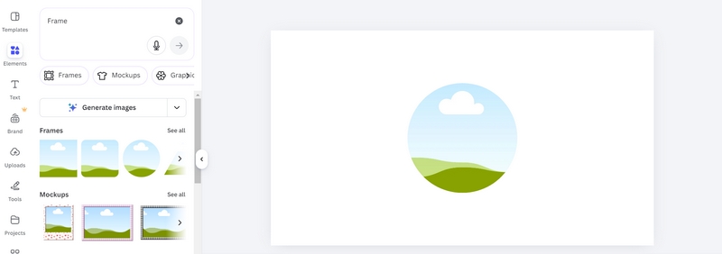
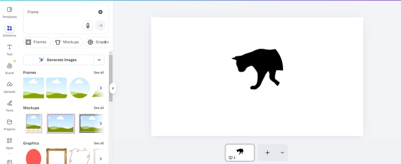
I needed the cat to fit into the tunnel. So I went to Canva and used the circular frame to crop the cat in a circle.
Next, I produced the Inkscape file and prepared it for printing.
Before proceeding to the next step, Gleb suggested that I test my idea on a scrap piece of fabric. I wanted to use a black piece of vinyl for the tunnel and a grey reflective piece for the cat. It's hard to say how the sheets of vinyl would interact with each other (the colours may bleed through) and how the final product would look, so it's a good idea to test first. I found someone's draft design on black vinyl among the scrap pile, which I then pressed into the fabric. I also cut two small squares out of the reflective material I wanted to use and pressed them on top.
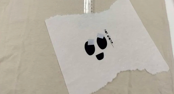
It seemed like the pieces interacted quite well and I liked how they looked, so I went on to print my design.
I exported the file to CutStudio to be printed. It's important to note that you should always mirror your design horizontally before printing. This is because the device cuts on the back of the material, and you need to flip it over before transferring it to the fabric.
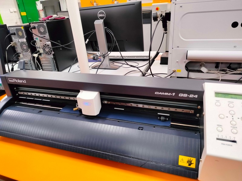
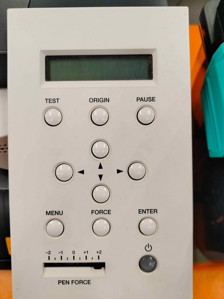
I placed the roll of vinyl behind the device and fed the sheet into it. Next, I aligned the pinch rollers with the grit marks. This should be done while taking the size of the design into account, and it is a necessary step to ensure the vinyl is secure and moves straight. From the control panel, I selected Roll for the roll of vinyl used and set up the origin. Unlike the laser cutter where the origin is typically set to the top left, here the origin is set to the bottom left corner. After this intial setup, I started the print.
The cut is very precise and not quite apparent to the eye. I cut around the design to separate it from the roll, then used twizzers to peel off the vinyl surrounding it. Here is what it looked like after the process:
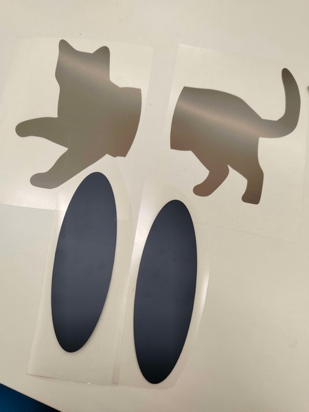
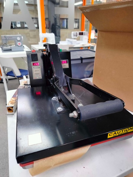
The design was now ready to be heat-pressed onto the T-shirts. I set the temperature to 140 degrees and the time to 15 seconds. When it reached the set temperature, I placed my T-shirt on the surface, taking care not to touch my hand to the hot plate, and the black circle on top of it. I closed the machine. After 15 seconds, it started singing very loudly, signalling its end. I opened the machine and removed the T-shirt. For the next step, you need to wait for the fabric to cool before peeling off the plastic, or the vinyl might come with it.
Then I repeated the process with the cat on top of the tunnel. When pressing for the second time, you need to place a baking sheet to cover the design as there is no plastic covering on the initial design. In my case, it was not necessary as the plastic on the cat design was big enough to cover the tunnel as well, but I used the baking sheet anyway.
The final design was a cute pair of matching T-shirts.
Design Files
Autodesk Fusion Files:
Box Top
Box Base
Transparent Hexagon
Red Hexagon
Inkscape Files
Transparent Hexagon DXF
Red Hexagon DXF
Cat Box SVG
Cat Tunnel T-shirt SVG

Learning Outcomes
- 3D modelling for printing
- Constraints in Autodesk Fusion
- Basics of laser cutting and how to prepare designs for it
- Using a vinyl cutter and heat press machine
Reflection
Overall, this was a very hectic but enjoyable week for me. I have learned how to work two completely new machines I have never even seen before in my life, and I consider that to be a great achievement. The professors were very patient and helpful throughout the whole process. The final products at the end of the week were simple but I am very happy with the results.